MPI-530
- Description
Professional and versatile
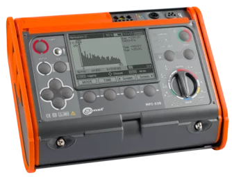
The multifunctional meter of parameters of electrical installations Sonel MPI-530 is used for precise measurements of electrical installations. The device has been constructed in compliance with the requirements of EN 61557 standard. It makes it possible to carry out all measurements connected with protection against electric shock described in the HD 60364-6 standard.
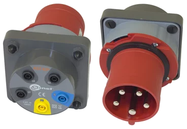
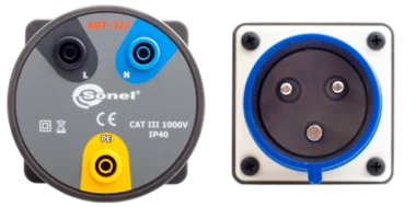
The Sonel MPI-530 specialised meter is distinguished by extensive ground measurement functions - additional clamp methods and soil resistivity. Using the optional AuroISO-1000C adapter, automatic insulation resistance measurements are also possible in sockets and for 3-, 4- and 5-core cables.
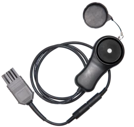
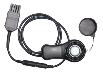
With the use of the Sonel MPI-530 meter it is also possible to test the illumination intensity. An additional external probe is required for this purpose. The instrument can record and analyse network parameters - including harmonics up to 40th. Another advantage of the meter is the robust IP54 casing, which protects the device from mechanical damage, dust or splashing.
Features
The meter offers a wide range of functionalities. It combines the measuring capabilities of several devices, while ensuring equally good accuracy.
- MPI-530 can be used for all measurements for commissioning of electrical installations in accordance with applicable regulations:
- short circuit loop impedance (also in circuits secured with RCDs),
- RCD parameters, » insulation resistance,
- earth resistance (4 measurement methods + soil resistivity measurement),
- continuity of protective and equipotential bondings,
- light intensity measurement,
- phase sequence test, » motor rotation direction test.
- MPI-530 can record 50/60 Hz power quality parameters:
- voltage L1 – average values in the range up to 500 V,
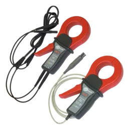
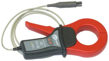
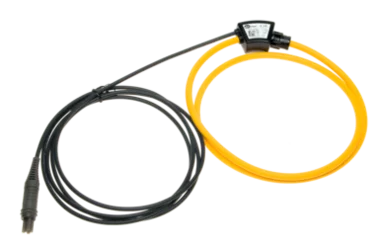
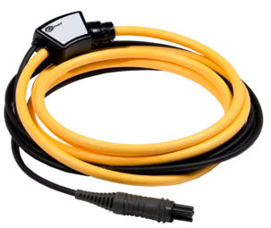
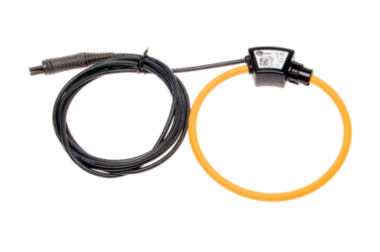
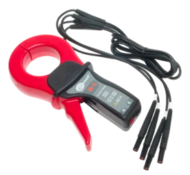
- L1 current – average values, current measurement in the range up to 3 kA (depending on the current probes used),
- frequency in the range of 40 Hz – 70 Hz,
- active (P), reactive (Q) and apparent (S) power,
- power factor (PF), cosφ,
- harmonics (up to 40th for voltage and current),
- total harmonic distortion (THD) for current and voltage.
Inspection of electrical safety
This device may be used to inspect safety of electrical systems in households and industrial facilities. Measurements can be easily automated with:
- auto mode of residual current devices (RCD) tests,
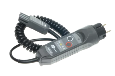
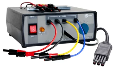
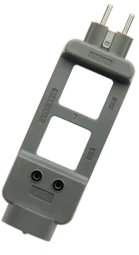
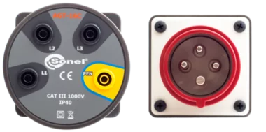
- the WS adapter that can be used for testing systems via standard 230 V sockets,
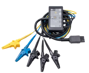
- AutoISO-1000C adapter for automatic insulation resistance test of 3-, 4- and 5-conductor cables, without switching.
Memory structure
The memory structure has a tree form. It has the ability to store tens of thousands of results in the configuration of CLIENT-OBJECT-FACILITY-MEASURING POINT, which helps to create a clear test protocol during later stages. This structure may be prepared in the meter, before starting the work. Entering data into the device is facilitated by QWERTY keyboard with Bluetooth communication module.
Built-in help system
The device has built-in help screens with measurement diagrams. Thanks to this you can easily and quickly check and make sure how to connect to a given system depending on the type of performed measurement.
Increased resistance to environmental conditions
The MPI-530 meter will cope well in difficult environmental conditions. Protection against penetration of dust and water is ensured by a unique housing with a level of protection IP54. It is resistant to mechanical damage, and a special design allows you to easily protect the screen by shielding using the cover of the meter. In addition to the fact that it protects against damage, it also allows you to conveniently carry and use the device in different positions.
Communication and software
You can easily transfer measurement data to your computer via USB port or Bluetooth wireless communication. In order to generate a report on measurements for electric shock protection, use Sonel Reports PLUS software. Saving the downloaded data to the simplest formats and printing is provided by free Sonel Reader software
- MPI-530 can be used for all measurements for commissioning of electrical installations in accordance with applicable regulations:
- Technical Specification
Measurement functions Measurement range Display range Resolution Accuracy Fault loop impedance Fault loop ZL-PE, ZL-N, ZL-L 0.13 Ω…1999.9 Ω acc. to IEC 61557 0,00 Ω…1999 Ω from 0.001 Ω from ±(5% m.v. + 0.03 Ω) Fault loop ZL-PE in RCD mode from 0.50 Ω…1999 Ω acc. to IEC 61557 0,00 Ω…1999 Ω from 0.01 Ω from ±(6% m.v. + 5 digits) Measurements of RCD parameters RCD tripping test and measurement of tripping time tA measuring current 0.5 IΔn, 1 IΔn, 2 IΔn, 5 IΔn general and short-time delay RCD • TN / TT mains 0 ms…300 ms 0 ms…300 ms 1 ms ±(2% m.v. + 2 digits) selective RCD 0 ms…500 ms 0 ms…500 ms 1 ms ±(2% m.v. + 2 digits) Measurement of RCD tripping current IA measuring current 0.2 IΔn…2.0 IΔn for sinusoidal residual current (AC type) 3.3 mA…1000 mA 3.3 mA…1000 mA from 0.1 mA ±5% IΔn for unidirectional residual current and unidirectional with the 6 mA DC bias (type A) 3.5 mA…700 mA 3.5 mA…700 mA from 0.1 mA ±10% IΔn for direct residual current (type B) 2.0 mA…1000 mA 2.0 mA…1000 mA from 0.1 mA ±10% IΔn Earth resistance 3- and 4-pole method from 0.50 Ω…1.99 kΩ acc. to IEC 61557-5 0.00 Ω…1.99 kΩ from 0.01 Ω from ±(2% m.v. + 3 digits) 3-pole + clamp method 0.00 Ω…1.99 kΩ 0.00 Ω…1.99 kΩ from 0.01 Ω ±(8% m.v. + 4 digits) 2-clamp method 0.00 Ω…99.9 kΩ 0.00 Ω…99.9 kΩ from 0.01 Ω from ±(10% m.v. + 4 digits) Resistance-to-earth 0.0 Ωm…99.9 kΩm 0.0 Ωm…99.9 kΩm from 0.1 Ωm Depending on accuracy of RE measurement Insulation resistance Measuring voltage 50 V 50 kΩ…250 MΩ acc. to IEC 61557-2 0 kΩ…250 MΩ from 1 kΩ from ±(3% m.v. + 8 digits) Measuring voltage 100 V 100 kΩ…500 MΩ acc. to IEC 61557-2 0 kΩ…500 MΩ from 1 kΩ from ±(3% m.v. + 8 digits) Measuring voltage 250 V 250 kΩ…999 MΩ acc. to IEC 61557-2 0 kΩ…999 MΩ from 1 kΩ from ±(3% m.v. + 8 digits) Measuring voltage 500 V 500 kΩ…2.00 GΩ acc. to IEC 61557-2 0 kΩ…2.00 GΩ from 1 kΩ from ±(3% m.v. + 8 digits) Measuring voltage 1000 V 1000 kΩ…9.99 GΩ acc. to IEC 61557-2 0 kΩ…9.99 GΩ from 1 kΩ from ±(3% m.v. + 8 digits) Resistance of protective conductors and equipotential bondings Measurement of resistance of protective conductors and equipotential bondings with ±200 mA current 0.12 Ω…400 Ω acc. to IEC 61557-4 0.00 Ω…400 Ω from 0.01 Ω ±(2% m.v. + 3 digits) Measurement of resistance with low current 0.0 Ω…1999 Ω 0.0 Ω…1999 Ω from 0.1 Ω ±(3% m.v. + 3 digits) Light intensity Measurement in luxes (lx) 0 lx…399.9 klx 0 lx…399.9 klx from 0.001 lx from ±(2% m.v. + 5 digits) Measurement in feet-candles (fc) 0 fc…39.99 kfc 0 fc…39.99 kfc from 0.001 fc from ±(2% m.v. + 5 digits) Phase sequence indication in the same direction (correct), opposite direction (incorrect), UL-L voltage: 95 V…500 V (45 Hz…65 Hz) “m.v.” - measured value
1-phase power quality recorder
The device is designed to work with mains:
- with nominal frequency 50/60 Hz
- with nominal voltage: 110/190 V, 115/200 V, 127/220 V, 220/380 V, 230/400 V, 240/415 V
Supported systems:
- single-phase
Parameter Measuring range Max. resolution Accuracy Alternating voltage (TRMS) 0.0…500 V 0.1 V from ±(2% m.v. + 2 digits) Alternating current (TRMS) depending on clamp* 0.1 mA from ±(5% m.v. + 3 digits) (error does not account for clamp error) Frequency 45.0…65.0 Hz 0.1 Hz ±(0.1% m.v. + 1 digit) Active, reactive, apparent and distortion power 0 VA…1.5 MVA, 0 W…1.5 MW, 0 var…1.5 Mvar 1 VA, 1 W, 1 var from ±(7% m.v. + 3 digits) cosφ and power factor (PF) 0.00…1.00 0.01 unspecified Harmonics Voltage 0.0…500 V 0.1 V from ±(5% m.v. + 3 digits) Current depending on clamp* as for alternating current True RMS from ±(5% m.v. + 3 digits) (error does not account for clamp error) THD Voltage 0.0…999.9% (in relation to the first harmonic) 0.1% ±5% Current 0.0…999.9% (in relation to the first harmonic) 0.1% ±5% (error does not account for clamp error) *- F-1A, F-2A, F-3A clamp : 0…3000 A AC (10 000 Ap-p)
- C-3 clamp: 0…1000 A AC (3600 Ap-p)
- C-6A clamp: 0..10 A AC (36 Ap-p)
- Files
- Firmware MPI-530changelog
- Improved memory structure
- Fixed minor bugs in the interface