
- Description
Professional measurements for every budget
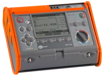
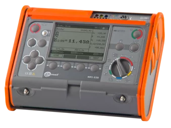
Versatile yet simple to use, the Sonel MPI-520 multifunctional meter for electrical installations performs its tasks flawlessly when measuring the parameters of electrical installations. The instrument has been developed to meet the needs of installers as well as measurement engineers. Intuitive operation will allow beginners to use the device, while advanced measuring capabilities will meet the expectations of the most demanding specialists. A number of modern solutions have been applied in the meter, which translate into additional functions and greater capabilities of the device.
In this way the Sonel MPI-520 meter significantly improves the performance of measurements of electrical installations.
The cost-effective and versatile Sonel MPI-520 meter is a proven choice for users looking for a simple to use, precise instrument that combines functions of several devices for electric shock measurements. With the use of one meter, it is possible to perform the measurement of short-circuit loop impedance (also in circuits with RCD switches), the measurement of earth resistance as well as testing of parameters of residual current devices, types AC, A and B. Extended capabilities, precision of measurements and application of pioneer solutions combined with a favourable price make this model of the meter a proven and reliable choice.
Features
The meter offers a wide range of functionalities. It combines the measuring capabilities of several devices, while ensuring equally good accuracy. The device can be used for all measurements for commissioning of electrical installations in accordance with applicable regulations:
- short circuit loop impedance (also in circuits secured with RCDs),
- RCD parameters,
- insulation resistance,
- earth resistance (3-pole method),
- continuity of protective and equipotential bondings,
- phase sequence test,
- AC voltage and AC current, frequency,
- cosφ, active (P), reactive (Q) and apparent (S) power (using clamp).
Additional functions
- Checking the correctness of PE connection using a contact electrode.
- Measurement of voltage (0 … 500 V) and network frequency.
- Memory of 990 results.
- Wireless data transmission to a computer.
Application areas
MPI-520 is simple in design and use, providing user with many measurement options. It may be successfully used to test household and industrial electrical systems.
Inspection of electrical safety
Measurements can be easily automated with:
- auto mode of residual current devices (RCD) tests,
- the WS adapter that can be used for testing systems via standard 230 V sockets,
- AutoISO-1000C adapter for automatic insulation resistance test of 3-, 4- and 5-conductor cables, without switching.
Increased resistance to environmental conditions
The meter will cope well in difficult environmental conditions. Protection against penetration of dust and water is ensured by a unique housing with a level of protection IP54. It is resistant to mechanical damage, and a special design allows you to easily protect the screen by shielding using the cover of the meter. In addition to the fact that it protects against damage, it also allows you to conveniently carry and use the device in different positions.
Communication and software
You can easily transfer measurement data to your computer via USB port or wireless communication. In order to generate a report on measurements for electric shock protection, use Sonel Reports PLUS software. Saving the downloaded data to the simplest formats and printing is provided by free Sonel Reader software.
- Technical specification
Measurement functions Measurement range Display range Resolution Accuracy Fault loop impedance Fault loop ZL-PE, ZL-N, ZL-L 0.13 Ω…1999 Ω acc. to IEC 61557 0.00 Ω…1999 Ω from 0.01 Ω ±(5% m.v. + 3 digits) Fault loop ZL-PE in RCD mode from 0.50 Ω…1999 Ω acc. to IEC 61557 0.00 Ω…1999 Ω from 0.01 Ω from ±(6% m.v. + 5 digits) Measurements of RCD parameters RCD tripping test and measurement of tripping time tA
measuring current 0,5 IΔn, 1 IΔn, 2 IΔn, 5 IΔngeneral and short-time delay RCD 0 ms…300 ms 0 ms…300 ms 1 ms ±(2% m.v. + 2 digits) selective RCD 0 ms…500 ms 0 ms…500 ms 1 ms ±(2% m.v. + 2 digits) Measurement of RCD tripping current IA
measuring current 0.2 IΔn…2.0 IΔnfor sinusoidal residual current (AC type) 3.0 mA…1000 mA 3.0 mA…1000 mA from 0.1 mA ±5% IΔn for unidirectional residual current and unidirectional with the 6 mA DC bias (type A) 3.5 mA…700 mA 3.5 mA…700 mA from 0.1 mA ±10% IΔn for direct residual current (type B) 2.0 mA…1000 mA 2.0 mA…1000 mA from 0.1 mA ±10% IΔn Earth resistance 3-pole method from 0.5 Ω…1.99 kΩ acc. to IEC 61557-5 0.00 Ω…1.99 kΩ from 0.01 Ω from ±(2% m.v. + 3 digits) Insulation resistance Measuring voltage 50 V 50 kΩ…250 MΩ acc. to IEC 61557-2 0 kΩ…250 MΩ from 1 kΩ from ±(3% m.v. + 8 digits) Measuring voltage 100 V 100 kΩ…500 MΩ acc. to IEC 61557-2 0 kΩ…500 MΩ from 1 kΩ from ±(3% m.v. + 8 digits) Measuring voltage 250 V 250 kΩ…999 MΩ acc. to IEC 61557-2 0 kΩ…999 MΩ from 1 kΩ from ±(3% m.v. + 8 digits) Measuring voltage 500 V 500 kΩ…2.00 GΩ acc. to IEC 61557-2 0 kΩ…2,00 GΩ from 1 kΩ from ±(3% m.v. + 8 digits) Measuring voltage 1000 V 1000 kΩ…3.00 GΩ acc. to IEC 61557-2 0 kΩ…3,00 GΩ from 1 kΩ from ±(3% m.v. + 8 digits) Resistance of protective conductors and equipotential bondings Measurement of resistance of protective conductors and equipotential bondings with ±200 mA curren 0.12 Ω…400 Ω acc. to IEC 61557-4 0.00 Ω…400 Ω from 0.01 Ω ±(2% m.v. + 3 digits) Measurement of resistance with low current 0,0 Ω…1999 Ω 0,0 Ω…1999 Ω from 0.1 Ω ±(3% m.v. + 3 digits) Phase sequence indication in the same direction (correct). opposite direction (incorrect). UL-L voltage: 95 V…500 V (45 Hz…65 Hz) Power measurement 0.0 VA…200 000 VA, 0.0 W…200 000 W, 0.0 var…200 000 var 0.0 VA…200 000 VA, 0.0 W…200 000 W, 0.0 var…200 000 var from 0.1 VA, from 0.1 W, from 0.1 var from ±(7% m.v. + 3 digits) “m.v.” - measured value
- Standard accessories
- Optional accessories
- Files