


- Description
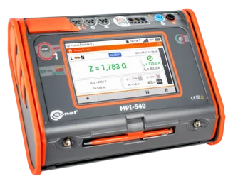
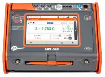
The MPI-540 multifunctional meter is intended for testing home and industrial electrical installations. The instrument can be used to carry out measurements, the results of which determine the safety status of the installation. In addition, the user is able to record the parameters of the electrical networks located at these sites. This makes it possible to control the quality of electricity, and to measure electric shock protection parameters, using a single universal device.
Significant automation of measurements is made possible by the function of testing residual current circuit breakers in Auto mode, as well as measurement sequences pre-programmed by the manufacturer (so-called autotests), which can also be extended with own sequences. Automatic measurement of insulation resistance of 3-, 4- and 5-core cables will be carried out with the AutoISO-1000C adapter.
Much more than a multifunctional meter
- The largest touch screen on the market (7”) – remarkable ergonomics and ease of use
- Removable microSD memory card – easy increase of memory capacity
- Li-Ion battery – longer operation of the meter
- Three-phase power recorder – advanced power quality diagnostics
- Real time display of network parameters – immediate evaluation of the test site conditions
- Parameters measured in accordance to class S of EN 61000-4-30 standard – high accuracy of measurements
- Energy cost calculator – quick evaluation of potential savings
- Measurement of all parameters related to earthing and protection against electric shock – one device instead of several
- Quick measurement of the fault loop impedance in networks secured with RCD without triggering (up to several seconds) – time saver
- Auto measurements – the ability to perform automatic measurements in sequence – simplified measurements • Fast path from measurements to report – time saver
Features
The meter has above-average functionality. It combines the measuring capabilities of several devices, while ensuring equally good accuracy.
- MPI-540 can record 50/60 Hz power quality parameters in accordance to S class of EN 61000-4-30:
- voltage L1, L2, L3, – average values in the range up to 500 V, » L1, L2, L3 currents, – average values, current measurement in the range up to 3 kA (depending on the current probes used),
- frequency in the range of 40 Hz – 70 Hz,
- active (P), reactive (Q) and apparent (S) power,
- power factor (PF), cosφ, tanφ,
- harmonics (up to 40th for voltage and current),
- total harmonic distortion (THD) for current and voltage,
- recording of events for current and voltage,
- energy flow – 4 quadrants.
- MPI-540 can be used for all measurements for commissioning of electrical installations in accordance with applicable regulations:
- short circuit loop impedance (also in circuits secured with RCDs),
- RCD parameters,
- insulation resistance,
- earth resistance (4 measurement methods + soil resistivity measurement),
- continuity of protective and equipotential bondings,
- light intensity measurement,
- phase sequence test,
- motor rotation direction test.
Automatic installation safety test
MPI-540 allow safety control of residential, commercial and industrial electrical installations. Measurements can be easily automated with:
- auto mode of residual current devices (RCD) tests,
- auto measurements – freely configurable measuring sequences,
- AutoISO-1000C adapter for automatic insulation resistance test of 3-, 4- and 5-conductor cables, without switching.
Three-phase power quality recorder
The device has a three-phase power quality recorder with the LIVE mode view and the possibility to register electrical network parameters such as voltage, current, power, harmonics and THD. The meter enables reading of selected parameters and their graphic presentation on the screen in real time. These parameters are measured and displayed concurrently with the recording on the memory card. In the LIVE mode, the user can see:
- voltage and current waveforms (oscilloscope),
- voltage and current timeplots,
- a phasor graph,
- display of multiple parameters in tabular form,
- spectrum graph of current and voltage harmonics.
Ease of reading
The device is equipped with a color TFT LCD touch screen with a resolution of 800x480 pixels and a diagonal of 7”, which allows for convenient operation and easy reading of parameters and plotted waveforms. This screen size enables displaying more information, available at any time of use. The interface is visible in all conditions – also thanks to the appropriate size of displayed symbols. Included stylus allows to work also with dielectric gloves.
Built-in help system
The device has built-in help screens with measurement diagrams. Thanks to this you can easily and quickly check and make sure how to connect to a given system depending on the type of performed measurement.
Increased resistance to environmental conditions
The MPI-540 meter will cope well in difficult environmental conditions. Protection against penetration of dust and water is ensured by a unique housing with a level of protection IP51. It is resistant to mechanical damage, and a special design allows you to easily protect the touch screen by shielding using the cover of the meter. In addition to the fact that it protects against damage, it also allows you to conveniently carry and use the device in different positions.
Communication and software
A very strong feature of the device is the multitude of communication interfaces and cooperation with external software. You can easily transfer measurement data to your computer via USB port, removable SD memory card, or wireless communication (Bluetooth, Wi-Fi ). In order to generate a report on measurements for electric shock protection, use Sonel Reports PLUS software. Saving the downloaded data to the simplest formats and printing is provided by free Sonel Reader software. The specialized, free Sonel Analysis software is used to read and analyze data from the power quality recorder.
- Technical specification
Specifications – electrical installation parameters
Measurement functions Measurement range Display range Resolution Accuracy Fault loop impedance Fault loop ZL-PE, ZL-N, ZL-L 0.13 Ω…1999.9 Ω acc. to IEC 61557 0.00 Ω…1999 Ω from 0.001 Ω ±(5% m.v. + 30 digits) Fault loop ZL-PE in RCD mode from 0.50 Ω…1999 Ω acc. to IEC 61557 0.00 Ω…1999 Ω from 0.01 Ω from ±(6% m.v. + 5 digits) Measurements of RCD parameters RCD tripping test and measurement of tripping time tA measuring current 0.5 IΔn, 1 IΔn, 2 IΔn, 5 IΔn general and short-time delay RCD 0 ms…300 ms 0 ms…300 ms 1 ms from ±(2% m.v. + 2 digits) selective RCD 0 ms…500 ms 0 ms…500 ms 1 ms from ±(2% m.v. + 2 digits) Measurement of RCD tripping current IA measuring current 0 0.2 IΔn…2.0 IΔn for sinusoidal residual current (AC type) 3.3 mA…1000 mA 3.3 mA…1000 mA from 0.1 mA ±5% IΔn for unidirectional residual current and unidirectional with the 6 mA DC bias (type A) 3.5 mA…700 mA 3.5 mA…700 mA from 0.1 mA ±10% IΔn for direct residual current (type B) 2.0 mA…1000 mA 2.0 mA…1000 mA from 0.1 mA ±10% IΔn Earth resistance 3- and 4-pole method from 0.50 Ω…1.99 kΩ acc. to IEC 61557-5 0.00 Ω…1,99 kΩ from 0.01 Ω from ±(2% m.v. + 3 digits) 3-pole + clamp method 0.00 Ω…1.99 kΩ 0.00 Ω…1.99 kΩ from 0.01 Ω from ±(2% m.v. + 4 digits) 2-clamp method 0.00 Ω…99.9 kΩ 0.00 Ω…99.9 kΩ from 0.01 Ω from ±(10% m.v. + 4 digits) Resistance-to-earth 0.0 Ω m…99.9 kΩm 0.0 Ωm…99.9 kΩm from 0.1 Ωm Depending on accuracy of RE measurement Insulation resistance Measuring voltage 50 V 50 kΩ…250 MΩ acc. to IEC 61557-2 0 kΩ…250 MΩ from 1 kΩ from ±(3% m.v. + 8 digits) Measuring voltage 100 V 100 kΩ…500 MΩ acc. to IEC 61557-2 0 kΩ…500 MΩ from 1 kΩ from ±(3% m.v. + 8 digits) Measuring voltage 250 V 250 kΩ…999 MΩ acc. to IEC 61557-2 0 kΩ…999 MΩ from 1 kΩ from ±(3% m.v. + 8 digits) Measuring voltage 500 V 500 kΩ…2.00 GΩ acc. to IEC 61557-2 0 kΩ…2.00 GΩ from 1 kΩ from ±(3% m.v. + 8 digits) Measuring voltage 1000 V 1000 kΩ…4.99 GΩ acc. to IEC 61557-2 0 kΩ…9.99 GΩ from 1 kΩ from ±(3% m.v. + 8 digits) Resistance of protective conductors and equipotential bondings Measurement of resistance of protective conductors and equipotential bondings with ±200 mA current 0.12 Ω…400 Ω acc. to IEC 61557-4 0.00 Ω…400 Ω from 0.01 Ω ±(2% m.v. + 3 digits) Measurement of resistance with low current 0.0 Ω…1999 Ω 0.0 Ω…1999 Ω from 0.1 Ω ±(3% m.v. + 3 digits) Light intensity Measurement in luxes (lx) 0 lx…399.9 klx 0 lx…399.9 klx from 0.001 lx from ±(2% m.v. + 5 digits) Measurement in feet-candles (fc) 0 fc…39.99 kfc 0 fc…39.99 kfc from 0.001 fc from ±(2% m.v. + 5 digits) Phase sequence indication in the same direction (correct), opposite direction (incorrect), UL-L voltage: 95 V…500 V (45 Hz…65 Hz) “m.v.” - measured value
Specifications – 3-phase power quality recorder
The device is designed to work with mains:
- with nominal frequency 50/60 Hz
- with nominal voltage: 64/110 V, 110/190 V, 115/200 V, 127/220 V, 220/380 V, 230/400 V, 240/415 V, 254/440 V, 290/500 V
- DC networks
Supported systems:
- single-phase
- split-phase with common N
- three-phase – WYE with and without N conductor
- three-phase – Delta
Parameter Measuring range Max. resolution Accuracy Alternating voltage (TRMS) 0.0…500 V 0.01% Unom ±0,5% Unom Alternating current (TRMS) depending on clamp* 0.01% Inom ±2% m.v. if m.v. ≥ 10% Inom, ±2% Inom if m.v. < 10% Inom , (error does not account for clamp error) Frequency 40.00…70.00 Hz 0.01 Hz ±0.05 Hz Active, reactive, apparent and distortion power depending on configuration (transducers, clamps) 4 significant digits depending on configuration (transducers, clamps) Active, reactive and apparent energy depending on configuration (transducers, clamps) 4 significant digits as power error cosφ and power factor (PF) 0.00…1.00 0.01 ±0.03 Harmonics Voltage as for alternating voltage True RMS as for alternating voltage True RMS ±5% m.v. if m.v. ≥ 3% Unom, ±0,15% Unom if m.v. < 3% Unom Current as for alternating current True RMS as for alternating current True RMS ±5% m.v. if m.v. ≥ 10% Unom, ±0,5% Unom if m.v. < 10% Unom THD Voltage 0.0…100.0% (relative to RMS value) 0.1% ±5% Current 0.0…100.0% (relative to RMS value) 0.1% ±5% Unbalance factor 0.0…10.0% 0.1% ±0.15% (absolute error) *
- F-1A, F-2A, F-3A clamp: 0…3000 A AC (10 000 Ap-p)
- C-4A clamp: 0...1000 A AC (3600 Ap-p)
- C-5A clamp: 0...1000 A AC / 0...1400 A DC (3600 Ap-p)
- C-6A clamp: 0...12 A AC (36 Ap-p)
- C-7A clamp: 0...100 A AC (360 Ap-p)
- Standard accessories
- Optional accessories
- Files
Version 4.7.1:
New features:
- Added support for HWh hardware revision (applies to PQM-710/711).
Version 4.7.0:
New features:
- Added ability to enter higher Isc value for IEEE and Chilean reports.
Version 4.6.9:
New features:
- Added "sum of currents" parameter on phasors diagram in Live mode for PQM-700 (requires at least firmware 1.19).
- Added 50 harmonics support in Polish standards for PQM-700 (requires at least firmware 1.19).
- Added recording of supplied and received active powers (15-min) for user recordings and configurations with Polish and GOST standards for PQM-700 (requires at least firmware 1.19).
Fixes:
- Improved data export for CSV file.
- Improved backward compatibility.
- Minor bug fixes.
Version 4.6.8:
New features:
- Updated EN 50160:2022 standards settings.
Fixes:
- Fixed application crash which could occur during some recorded data loading.
- Fixed application crash during plots printing.
- Minor bug fixes.
Version 4.6.7:
New features:
- Updated Polish standards settings.
Fixes:
- Minor bug fixes.
Version 4.6.6:
New features:
- Added report generation according to IEEE 519:2022 standard for PQM-702(x)/703/710/711 (requires at least firmware 1.56).
Fixes:
- Improved recalculation of IL for TDD value in data analysis table.
- Minor bug fixes.
Version 4.6.5:
Fixes:
- Fixed mechanism for selecting 15-min samples in norm reports.
Version 4.6.4:
New features:
- Added new nominal voltage Un 346/600 V.
- Expanded micro-installations recommendation report.
Fixes:
- Fixed data exclusion in standards reports for PQM-702(x)/703/710/711 (requires at least firmware 1.55) and PQM-700 (requires at least firmware 1.18) recorded data.
- Fixed possibility to enable detection of waveshape variations and phase jumps events in half-period recording configurations for PQM-702(x)/703/710/711 (requires at least firmware 1.55).
- Improved recovery data mechanism.
- Minor bug fixes.Version 4.6.2:
New features
- added support for 4-quadrant energy meters for MPI-540 and MPI-540-PV recorded data (requires at least firmware 3.21);
- added new nominal voltage Un 462/800 V;
- increased micro-installations recommendation report.
Fixes:
- improved standard reports export;
- minor bug fixes.Version 4.5.0:
New features:
- Added support for the PQM-702/703 analyzers without the OR-1 interface.
Fixes:
- Translation fixes in Ukrainian language.Version 4.4.9:
New features:
- Added Ecuadorian standards for PQM-702(x)/703/710/711.
- Increased edit ability of the reports header.
Fixes:
- Implemented A3:2019 amendment to EN 50160 standard (requires restoring default values for "EN 50160:2010 + A3:2019 low voltage" standard in Program settings module).
- Fixed problem with reading NEC220.87 data.
- Improved user interface.
- Minor bug fixes.Changes in version 4.0.23.0 compared to the previous one:
- Improved communication with the MPI‑540.
- Updated libraries and applied minor fixes.
- Added support for MMR-6500E and MMR-6700E.
Changes in version 4.0.22.0 compared to the previous one:
- Improved communication with the MRU-30.
- Added serial number reading for the MPI-520 and MPI-525.
- Fixes realted to chart rendering and translations.
- Minor improvements enhancing overall program stabiltiy.
Changes in version 4.0.21.0 compared to the previous one:
- Improved visibility of the client selection window.
Changes in version 4.0.20.0 compared to the previous one:
- Improved communication with meters.
- Improved chart generation.
- Improved visibility of the client selection window.
- Firmware MPI-540 (4.01.14)changelogcomments
Changes in version 4.01.14 compared to the previous one:
- French language added.
- Improved sending of data from the meter via email.
- Improved transfer of structure from reporting programs to the meter.
- Improved stability.
Changes in version 3.26.06 compared to the previous one:
- Improvements in RISO measurements
- Improvements in ZRCD measurements.
- Improvements Z (EVSE) measurements.
- Improvements regarding sounds.
- Keyboard improvements.
- Ability to add folders in auto measurements.
Notes on the update from version 4.00.21:
1. Updating the meter from an older system version (below 4.0) to a newer one is only possible using an update file on a USB flash drive.
2. Updating the meter from an older system version to a newer one is irreversible for the user. You can only roll back updates within a given system version.